


Are the capacitors good or bad? Short circuit or open circuit? Handy 8 ways to test capacitors, understand in seconds
Today we are introducing to you: 8 ways to test capacitors for good or bad.
In most electrical and electronic troubleshooting and repair work, you will encounter a common capacitance problem, if you want to know how to test and check capacitance? Is a capacitor good or bad? Short or open circuit? Here you can use an analogue (AVO, Amps, Volts, Ohms) and digital multimeter to check that the capacitor is in good condition or replace it with a brand new one.
Here are 8 ways to check and test if a capacitor is good, defective, open, dead or shorted.
Method 1: Capacitance testing with a digital multimeter - resistance mode
To test capacitance with a DMM (digital multimeter) in resistance "Ω" or ohmic mode, follow these steps:
1. Ensure that the capacitor is fully discharged.
2. Set the meter to the ohmic range (at least to 1000 ohms = 1kΩ).
3, Connect the multimeter probe to the capacitance terminals (negative to negative and positive to positive).
4. The digital multimeter will display the value.
5. It will then immediately return to OL (open line) or infinity "∞".
Conclusion
If each attempt in step 2 shows the same result as shown in steps 4 and 5, this means that the capacitor is good, if not, then the capacitor is bad.
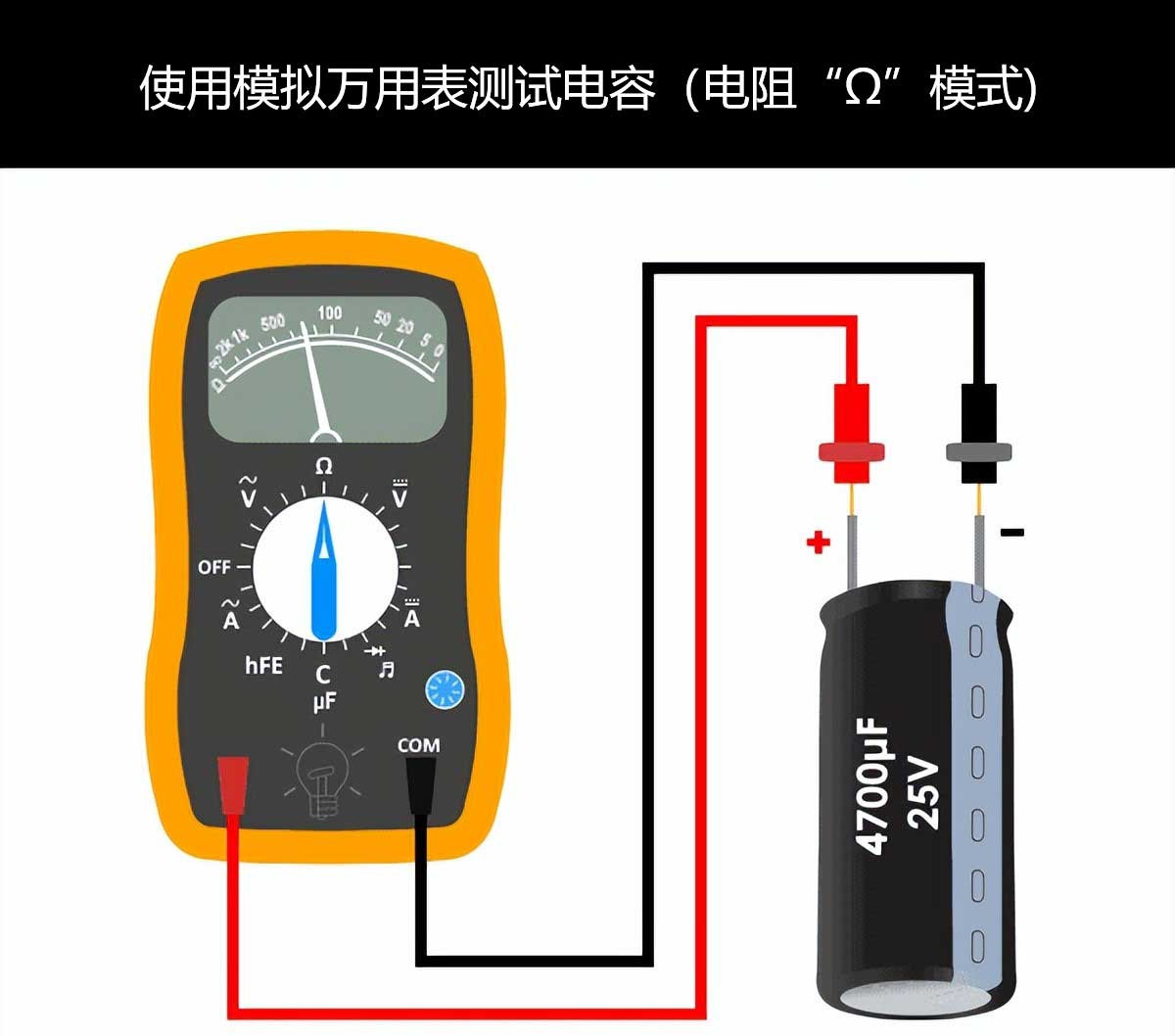
Method 2: Checking capacitance with an analogue multimeter - ohmic mode
To check capacitance with an AVO (Amp, Volt, Ohmmeter) in resistance "Ω" or Ohm mode, follow these steps
1. Make sure the suspect capacitor is fully discharged.
2. Take an AVO meter.
3. Turn the knob on the analogue meter to select the resistance "OHM" mode (always select the higher ohmic range).
4. Connect the multimeter leads to the capacitor terminals. (COM to "-Ve", positive to "+Ve") terminals).
5. Note the reading and compare it with the following results.
Conclusion:
Short circuit capacitance: a short circuit capacitor will show a very low resistance.
Open circuit capacitance: an open circuit capacitor will not show any movement (deflection) on the ohmmeter scale.
Good capacitance: Initially it will show a low resistance and then gradually increase to infinity. This means that the capacitor is in good condition.
Method 2: Checking capacitance with an analogue multimeter - ohmic mode
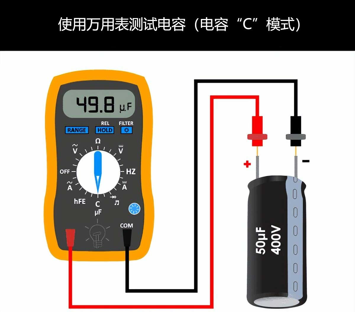
Method 3: Using the multimeter in capacitance mode to check capacitance
Note: Capacitance can only be tested in capacitance mode if the analogue or digital multimeter has a Farad "C" function for capacitance. The capacitance mode function of the multimeter can also be used to test tiny capacitances. To do this, turn the multimeter's knob to capacitance mode and follow the basic instructions below.
1. Ensure that the capacitor is completely discharged.
2. Remove the capacitor from the circuit board.
3. Now select capacitor "C" on the multimeter.
4. Now connect the capacitor terminals to the multimeter leads. (red to positive and black to negative).
5、If the reading is close to the actual value of the capacitor (i.e. the printed value on the capacitor container box).
6. Then the capacitor is in good condition. (Note that the reading may be less than the actual value of the capacitor (the capacitor is rated at ±10 or ±20 due to tolerances).
Conclusion:
If you read a significantly lower capacitance value or none at all, the capacitor is depleted and you should replace it with a new one to ensure proper operation.
Method 3: Using the multimeter in capacitance mode to check capacitance
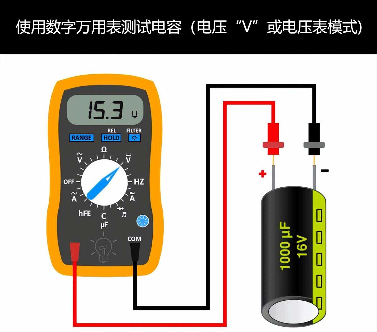
Method 4: Testing capacitors with a simple voltmeter
This method is applied to both polar and non-polar capacitors and the nominal voltage value of the capacitor must be known. The voltage rating is already printed on the nameplate of the electrolytic capacitor. Although specific codes are printed on ceramic and SMD capacitors, it is possible to follow the procedure below.
Alternatively, you can use the DC voltage "V" or voltage mode in a digital or analogue multimeter to perform this test.
1. Ensure that the single lead of the capacitor is disconnected from the circuit (don't worry about the positive (long) or negative (short) terminal) (you can also disconnect it completely if required)
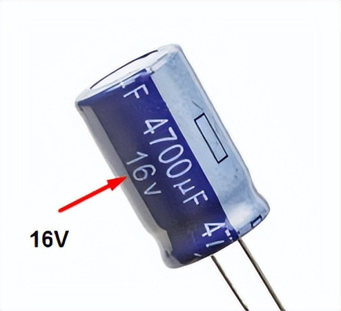
2. Check the voltage rating of the capacitor printed on it (as shown in the example below, voltage = 16V)
3. Now charge this capacitor for a few seconds to the rated value voltage. (Not the exact value but less than that, i.e. use a 9V battery to charge a 16V capacitor. If the battery voltage value is greater than the nominal voltage of the capacitor, it will damage or blow the capacitor.) Ensure that the positive (red) lead of the voltage source is connected to the positive lead (long) of the capacitor and the negative lead to the negative terminal.
4. Set the voltmeter value to DC voltage by connecting the positive lead of the battery to the positive lead of the capacitor and the negative lead to the negative terminal and the capacitor to the voltmeter. You can use a digital or analogue multimeter while selecting the DC voltage range for the same purpose.
Capacitance
Testing capacitance with a simple voltmeter
Conclusion:
Pay attention to the initial voltage reading in the voltmeter. If it is close to the supply voltage provided to the capacitor, the capacitor is in good condition. If it shows a much lower reading, then the capacitor is dead. Note that the voltmeter will show a reading in a very short time because the capacitor will release the voltage it has stored in the voltmeter.
Note: The capacitor voltage value should be less than the battery voltage. Otherwise the capacitor will explode or burn out.
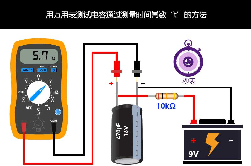
Method 5: Testing capacitance by measuring the value of the time constant
If the capacitance value of a capacitor is known in microfarads (symbol µF) printed on it, i.e. the capacitor does not fuse and burn at all, we can find the value of the capacitor by measuring the time constant (TC or τ = Tau).
In short, when a capacitor is charged through a resistor of known value, the time it takes for the capacitor to charge to approximately 63.2% of the applied voltage is called the capacitance time constant (τ = Tau also known as the RC time constant) and can be calculated by
τ = R x C
R = known value of resistance in ohms
C = value of capacitance
τ = Tau (time constant)
For example, if the supply voltage is 9V, then 63.2% of the supply voltage is at around 5.7V. We will use a stopwatch to charge the capacitor until the value reaches 5.7V, stop the watch and note the time reading in seconds.
Now, find the value of the capacitor by measuring the time constant (note: an oscilloscope uses exact values for better measurements)
1. Ensure that the capacitor is disconnected from the board and discharged.
2. Connect a known resistance value (e.g. 5-10kΩ resistance) in series with the capacitor.
3. Apply a known value of supply voltage. (e.g. 12V or 9V) to the capacitor in series with the 10kΩ resistor.
4. Now measure the time it takes for the capacitor to charge to approximately 63.2% of the applied voltage. For example, if the supply voltage is 9V, then 63.2% of this is approximately 5.7V.
5. Based on the value of the given resistance and the time measured by the stopwatch, calculate the capacitance value by using the time constant
formula to calculate the value of the capacitance, i.e. τ = Tau (time constant)
6. The calculated value of the capacitance is now compared with the electrical value printed on it.
Test capacitance by measuring the value of the time constant
Conclusion:
If the measured value is the same or almost equal to the value printed on it, the capacitance is in good condition. If you find a significant difference between the two values, the capacitor needs to be replaced as it is not operating correctly.
Example:
Suppose we want to test a 16V, 470µF capacitor. If the supply voltage is 9V, then 5.7V is 63.2% of the supply voltage. We connect the capacitor to the battery for charging and start the stopwatch. When the meter shows 5.7V we will stop the stopwatch. Assume that the stopwatch shows a duration of 4.7 seconds.
Now, measure the capacitance using the time constant τ = RC formula, i.e. C = τ / R
C = 4.7 seconds / 10kΩ
C = 0.47mF = 470μF
Now compare the calculated value of the capacitance with the value of the capacitance printed on it.
If the calculated value is almost equal to the required capacitor or differs by ±10 to ±20, the capacitance is good.
If the calculated values are very far apart and significantly different, the capacitor is faulty.
In our example, the calculated value is almost the same as the actual value of the capacitor, which means that the capacitor is in good condition.
The discharge time can also be calculated. In this case, the time it takes to discharge the capacitor to 36.8% of the peak voltage can be measured.
Tip: It is also possible to measure the time it takes to discharge the capacitor to around 36.8% of the peak voltage applied, and the discharge time can be found for the capacitor in the same way as in the formula.
Method 6: Testing capacitors by continuity test mode
In DMM and AVO meters, the continuity test mode can also be used whether the capacitor is good or open or short-circuited. This can be done by following these simple instructions.
1. Disconnect the power supply and remove the capacitor from the board.
2. Use a resistor to completely discharge the capacitor.
3、Turn the knob and set the multimeter to continuity test mode.
4. Connect the positive (RED) probe of the multimeter to the anode (+) terminal and the common (black) probe to the cathode (-) terminal of the capacitor.
5. If the multimeter shows signs of normal conduction (beep or LED) and suddenly stops and displays OL (open circuit). This means that the capacitor is in good condition.
Conclusion:
If the multimeter does not show an on sign with beep or LED, the capacitor is open. If the multimeter LED lights up and makes a continuous ticking sound, the capacitor is short-circuited and should be replaced with a new one.
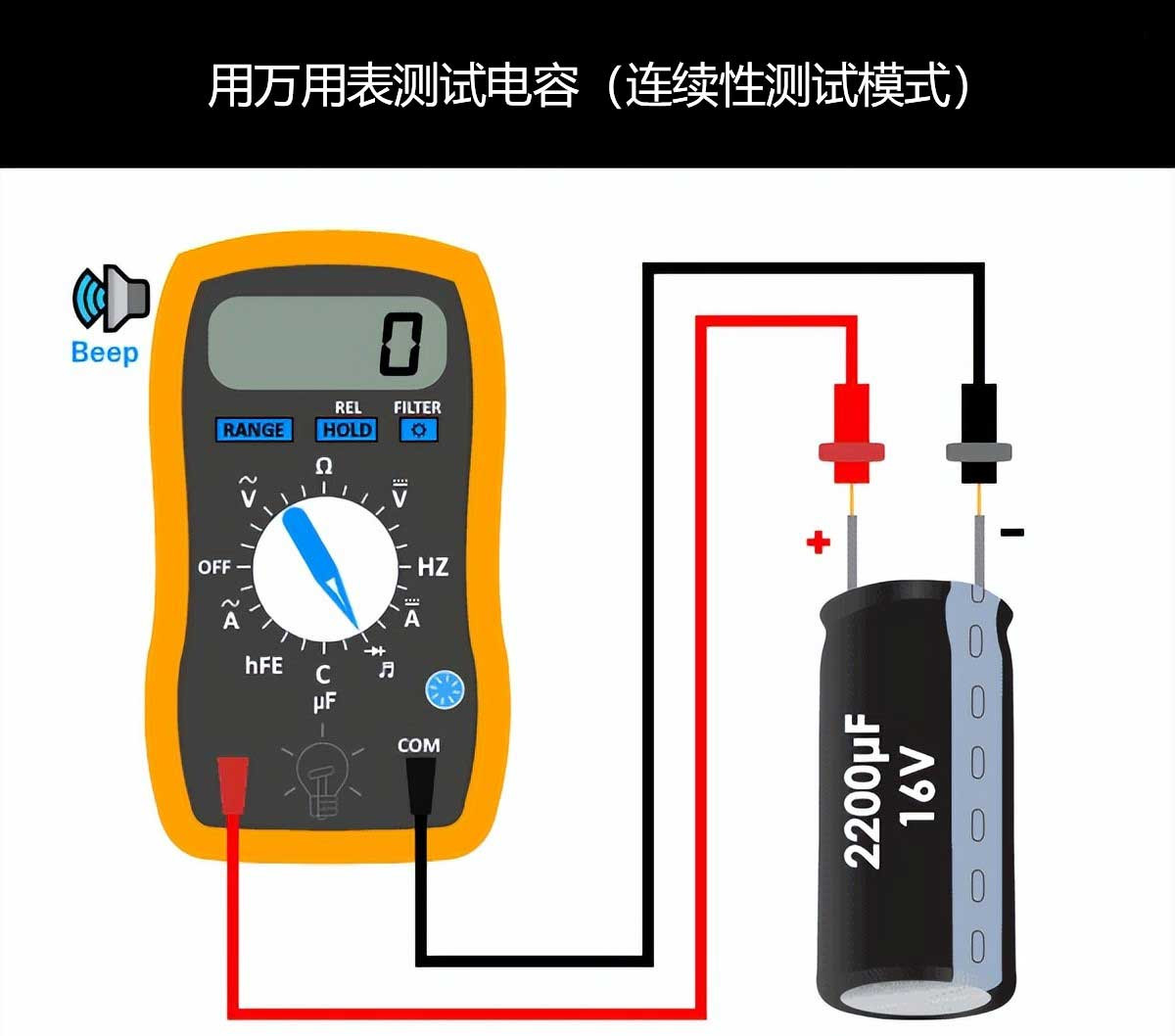
Test capacitance by continuity test mode
Method 7: Testing capacitors by visual and visual inspection
Observe the obvious signs that a capacitor appears to be faulty, which is obvious without using a multimeter. A capacitor has failed and is damaged if you find 2 things:
1.The top vent of the capacitor is bulging
The top vent hole of a K, T or X shaped electrolytic capacitor is a weak point for releasing pressure when the capacitor fails , to avoid serious damage to any other components around and connected to it.
If a bulge is found at the top of the capacitor, it is an electrolytic discharge (black, white, orange, depending on the electrolytic material), i.e. the capacitor releases gas pressure and damages the top vent of the capacitor in the event of failure.
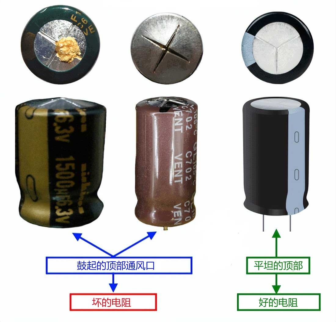
Bulging of the top vent of the capacitor
2. Capacitor bulging bottom lifts the case
If the gas pressure generated during a fault does not destroy the top vent of the capacitor, it will pass through the bottom and push the rubber, causing the bottom to bulge and lift the case.
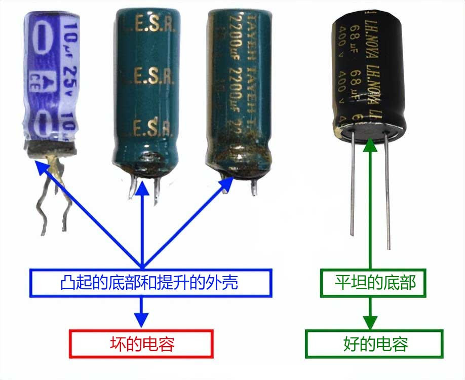
Capacitive drum bottom lift shell
3.Testing SMD and ceramic capacitors
If the following marks are found on ceramic or miniature SMD capacitors, they are faulty and need to be replaced with the correct capacitors.
Broken or cracked case.
Damage to the case or any signs of burning, a hole in the case.
Damaged terminals.
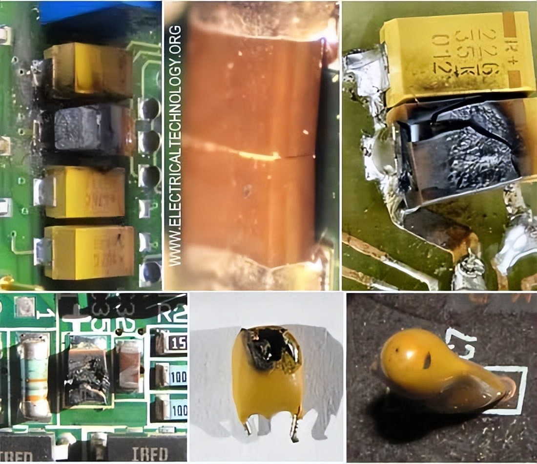
Testing SMD and ceramic capacitors
Method 8: Traditional method of testing and checking capacitors
Note: Not recommended for everyone, only for professionals, as it is more dangerous.
Safety precautions and warnings must be followed before applying this method. This method should only be used in emergency situations where there is no other option to check the capacitors for good or bad. If you are not sure, it is still recommended to troubleshoot the capacitor using methods 1-7.
If you want to check capacitors (e.g. fan capacitors, room air cooler capacitors or miniature capacitors in a circuit board/PCB etc.), test the capacitors by method 8.
For proper safety, use a 12 to 24V DC supply with polarised and non-polarised capacitors with 1kΩ to 10kΩ, 5 to 50W resistors. The resistor should be connected in series with the positive terminal of the battery and capacitor. This way it will reduce the excessive current when charging the capacitor.
In the absence of a DC supply (e.g. battery), you can use 120-230V AC, but a series of resistors (e.g. 1kΩ to 10kΩ, 5 to 50Watts) must be connected to connect the capacitor to the 230V AC supply. In this way it will reduce the charging and discharging current. Here is a step-by-step tutorial for checking the capacitors by this method.
1. Disconnect the suspect capacitor from the power supply or make sure that the capacitor has at least one lead disconnected from the PCB board.
2.Make sure the capacitor is fully discharged.
3.Connect two separate leads to the capacitor terminals. (Optional)
4. Now connect these leads safely to the 24VDC or 230V AC supply for a short time (approx. 1-4 seconds) [or for a short time when the voltage rises to 63.2% of the supply voltage].
5. Remove the safety lead from the 24VDC/230V AC supply.
6. Now short the capacitor termination (please be careful and ensure that you wear goggles)
Conclusion:
If it produces a strong spark, then the capacitor is good. If it produces a weak spark or no spark at all, then it is a defective capacitor.